I decided to start the series of posts dedicated for people who already know how to program in whatever programming language(C/C++ background is preferable) and willing to learn reverse engineering for x86 platform. If you never did programming, you can try to follow this guide as well, but you have to know something, at least what functions and variables are. I don’t want to linger on explaining the very basics, like what processor is and how it works, I’ll try to focus on keeping everything informative and concise.
Reverse engineering is obtaining information about how a system works without using information which specifies its design. In context of x86 platform, reverse engineering refers to the process when you have to realize how software(a program/library/OS kernel/driver) functions without reading source code. This is very perverted way to do this, and you normally go with this option when you have no access to source code, maybe it was lost or greedy programmers just don’t want to handle it to you.
Programming languages can be classified in 2 categories: high-level and low-level. Last one is usually called assembly language. High-level languages(Java, Python, C++, etc.) can help you write a program without considering what platform you are making program for. They were actually created for this. Programming in high-level languages introduces nothing but advantages for a programmer: you can write easy-to-understand(compared to assembly languages) code without focusing how specific platform works, and you can compile your program for any platform. Assembly language programming doesn’t offer this simplicity, and you have to take more time and effort to develop a program.
Remember, machine code is what compiler generates and puts in executable file. This output is just a lot of bytes to be interpreted by processor to make program work. Assembly language is the same as machine code, but in human-readable(not so human, in fact) form composed from a lot of instructions. So, if you had a sequence of bytes in executable file, it could be translated to a particular assembly instruction which multiplies one number with another.
Reverse engineering can be done in 2 ways: static and dynamic analysis. Static analysis is how you try to figure out what program does without running it, only using machine code which is stored in binary file. When you do dynamic analysis, you run a program(normally in debugger) to see how it works. For static analysis, there are already some tools which can ease reverse engineering process for you. These are some I know: Ghidra(I use it currently), IDA Pro, Binary Ninja, Hopper.
R.E. can help you understand what features the program has, how to disable/enable them, how to use them without having API, etc.
In this series part, I want to cover what registers and some instructions are, how conditions code is implemented in assembly language, and tell a bit about executable file formats for modern(Windows and Unix-like) operating systems.
Registers and Instructions
Registers are the preallocated memory cells inside processor that are used for operating on data. The difference between accessing registers(reading or writing to them) and accessing normal memory is normal memory access takes more time than register access.
You will often see me talking about “memory” here. When I say “memory” I normally talk about RAM, not HDD or SSD storage. RAM is the place where OS loads a program before execution. This is the list of access speed of different memory types in descending order:
-
registers;
-
RAM;
-
SSD;
-
HDD;
i.e. registers are most easy for processor to access, RAM takes a bit more time, and SSD and HDD are slowest to read or write.
In general, instructions with all their operands provided as registers, will execute faster than those having memory operands. This is due to the fact, that registers are already implemented within CPU by its own circuits. Instructions are commands with operands, which are transferred to the processor for execution. You can associate instructions with functions, the difference is the former perform very tiny work. As instruction operand, you can specify register, memory value at particular address using brackets, or immediate value, last one is just a number.
This is a small detour just to show what instructions are and what operands they can take:
MOV EAX, EBX                     ; this instruction transfers(MOVes) data in EBX register to EAX register
MOV EAX, dword ptr [0xDEADBEEF]  ; transfer a DWORD(4 bytes of memory) at memory address 0xDEADBEEF to EAX register
MOV EAX, 0xDEADBEEF              ; transfer 0xDEADBEEF number to EAX
“dword ptr” means “take value of address at”.
DWORD is name of memory unit containing 4 bytes. There are other units as well: BYTE(sometimes called halfword) is 1 byte, WORD is 2 bytes, DWORD(doubleword?) is 4 bytes, QWORD(quadraword?) is 8 bytes. “Word” is an old term in computer architecture: “In computing, a word is the natural unit of data used by a particular processor design. A word is a fixed-sized piece of data handled as a unit by the instruction set or the hardware of the processor."
Ideally, for a processor with 16-bit only registers, a word has 2 bytes of length; for 32-bit processors - word consists of 4 bytes. But in reality, when someone refers to something as “word”, it would always mean 2 bytes, despite what capability computer has to address memory: “Another example is the x86 family, of which processors of three different word lengths (16-bit, later 32- and 64-bit) have been released, while word continues to designate a 16-bit quantity."
Many instructions take 2 operands, or 1 operand, or none. 2-operands instructions have a source operand and destination operand, like in MOV. Instructions with one operand have it as destination operand. Why are “destination” and “source” operands called this way, you might ask? Most x86 instructions work this way: take a source operand, do some operation on operands(like adding), and put result in destination operand.

This is the assembly output of main() function in program.
And this is C code for the same program:
#include <stdio.h>
int a;

int main(){
    int b,c;
    a = 20;
    b = 45;
    c = 55;

    a *= b;
    a += c;

    printf("%d\n", a);
}
Disassembler is a program which prints processor instructions contained in binary file. Opposed to it, assembler composes a program from assembly source code.
You can see I didn’t comment the very first(PUSH RBP, etc.) and last instruction blocks of main() function. I’ll explain what they are for in next article.
Almost all disassemblers use Intel syntax to output program contents. Generally, it follows the rule to display destination operand on left side, and source on the right. AT&T syntax behaves differently, I myself prefer Intel syntax just because it looks clearer.
On x86 processors, registers are categorized in 3 groups: 8 general purpose registers, 6 segment registers, and 2 others(EIP and EFLAGS).
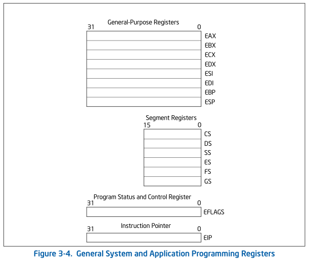
For registers and variables having N bits, all bits are grouped right-to-left, that is 0th bit starts at the very right side, and (N-1)th bit is at the very left side. 0th bit is also called Least Significant Bit(LSB), and (N-1)th bit is Most Significant Bit(MSB). “Significance” is just how much value a bit adds to the number contained in memory. For example, 0101(5 in decimal) is bigger than 0011(3 in decimal).
Segment registers are 16-bit only:
CS, DS, SS, ES, FS, GS.
They hold addresses where segments(segments of memory) start, also called as segment bases. On modern operating systems, they cannot be used that way as general purpose registers. Your program can’t read or write to them in non-kernel code. Most of times you don’t have to worry about them as they are generally not used in modern OS’s. But they are important for memory addressing in real mode, and segmentation, which you’ll read about later.
32-bit general purpose registers are:
EAX, EBX, ECX, EDX, ESI, EDI, EBP, ESP.
Those registers can contain numbers from 0 to 4,294,967,295 (2^32-1), which have to be stored with 32 bits at most.
There are also 16-bit general purpose registers:
AX, BX, CX, DX, SI, DI, BP, SP.
As you see, all 32-bit registers are prefixed with “E” letter, EIP and EFLAGS are also 32-bit. Perhaps they are called “general purpose” because you can use them as you wish, if you were to program in x86 assembly language. Except some cases when using instructions like MUL, DIV, LODS or any other operation which uses predefined set of registers. You can look up those instructions in Intel Manual Volume 2 to see what they do. You also can’t use EBP and ESP(you can, but processor won’t be happy about it) as normal general purpose registers because they are used by stack operations(POP, PUSH, ENTER, LEAVE). I’ll tell more about stack in next post.
I’ll leave references to Intel Manuals in the end of article, this should be your primary information source if you want to know more about anything related to x86 platforms.
64-bit processors can use 64-bit registers. Guess how they are called if prefix is “R” now. If you have answer like: RAX, RBX, RCX, RDX, RSI, RDI, RBP, RSP; you’re right. Don’t forget about RIP and RFLAGS. Also there are additional 8-byte registers R8, R9… R15 available only for 64-bit processors.
There are 8-bit registers as well, two of them for a corresponding 16-bit register.

Only thing you have to remember about them is all -H registers contain upper 8 bits of -X register, respectively -L registers contain lower 8 bits. Also, if you change -X, -H, or -L value, you also change corresponding E-X and R-X values because they all use the same space.
Suppose there’s a program that executes this code, comments show what values would take corresponding nested registers:
MOV RAX, 0x0123456789ABCDEF ; EAX = 0x89ABCDEF, AX = 0xCDEF, AH = 0xCD, AL = 0xEF
MOV EAX, 0x11992233         ; RAX = 0x0123456711992233, AX = 0x2233, AH = 0x22, AL = 0x33
Conditions
EFLAGS is the register containing flags. Flags are indicators of processor state. There’s a lot of them, but we’re only interested about those indicating results of arithmetic and bitwise instructions. These flags are called status flags.

EFLAGS is used to determine if program code’s condition is false or true. After this, program takes decision if it will run instructions in if-block code or it won’t. For example:
...
MOV EAX, 4
CMP EAX, 4
JNE goto
ADD EAX, 2
JMP goto_2

goto:
ADD EAX, 4
goto_2:
...
This is high-level code for assembly code above:
...
int a = 4;

if(a == 4)
a += 2;
else
a += 4;
...
JMP is called jump instruction. It changes direct execution flow, its operand tells the processor where the next instruction to run is. In other words, it “jumps” to another instruction. JNE is conditional jump, because it is executed only if its condition satisfies. Condition is always the state of one of the status flags.
CMP stands for “compare”, and JNE can be interpreted as Jump if Not Equal. That is, if EAX doesn’t equal to 4, then code flow should be directed to “goto” label. EAX equals to 4, so program adds 2 to EAX, and jumps to code with “goto_2” label, so that it doesn’t accidentally execute else-branch.
After CMP is executed, Zero Flag(ZF) equals to 1, indicating that CMP’s operands are equal. If they weren’t, ZF would be set to 0. Note: JNE can also be listed by disassembler as JNZ, both instructions are the same. Again, you can take a look at all of them in Intel Manual Volume 1, Appendix B.
EIP is the instruction pointer register. It contains the address of the next instruction to be executed. When (conditional) jump is done, EIP is changed to jump to instruction’s operand.
EFLAGS and EIP registers cannot be changed explicitly, i.e. you can’t assemble the program containing something like MOV EIP, EAX.
x86 Modes of Operation
Before I proceed to other topics, it would be useful to tell about modes of operation on x86 processors. It is not necessary to remember everything here, but maybe you’ll need it later.
Real Mode
The first Intel processors(Intel 8086, Intel 8088, etc.) had only one operation mode called real mode. “Real” probably means that program running in this mode can access any memory address, without software or hardware limitation. Real addresses are composed of 2 parts: base address and offset. These parts could only be 16-bit, because real mode was first used on 16-bit processors. To calculate the real address, it places the base to segment register(CS, DS, SS, etc.), and offset to general purpose register(AX, BX, CX, …) . After that, it multiplies base address by 16(or shifts it 4 bits left, it is the same operation), and adds it with offset. The final number is both real and linear address. Probably, Intel implemented addressing this way because it wanted their processors to use only 16-bit registers without adding 20-bit register for addressing.
As example, if you have base of 0x0123 and offset of 0x4, you get
(0x0123 << 4) + 0x4 = 0x1234
If you were to disassemble real-mode program, you would encounter instructions like this:
MOV AX, word ptr [DS:BX]
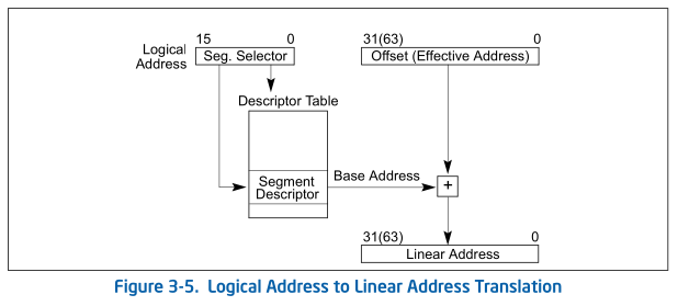
The 2nd operand refers to a 2-byte value at DS+BX address. SEGMENT + OFFSET can also be called logical address. Sometimes OFFSET is referred to as effective address.
The type of addressing when processor uses base and offset to refer to memory is called segmentation. At segmentation, all RAM is divided between segments(on 8086 each segment is 64 kilobytes long). With this scheme, 8086 processor can address no more than 1 megabyte of memory(2^20 bytes).
Protected Mode
In real mode, whole RAM can be accessed by a program without privilege checking. This is one of the drawbacks real mode has: if you write a buggy program that doesn’t operate on its memory correctly(it can access other programs' memory or even kernel), you should expect that something goes wrong with system. It doesn’t protect your system from malware either. Protected mode fixes it with “rings”.
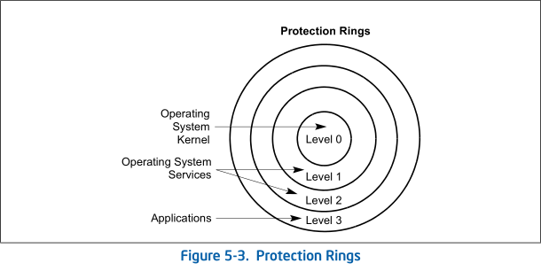
This is the term from computer science meaning “mechanism to protect data and functionality from faults and malicious behavior”.
One of the features of protected mode since Intel 80386(first 32-bit processor) is extended segment size, which gives you to use 4 gigabytes of memory. This is due to adding 32-bit registers as offsets. It also means that any segment can contain 4 gigabytes. Addressing with segmentation is still the same: you have 16-bit segment base in segment register, but 32-bit offset in general purpose register.
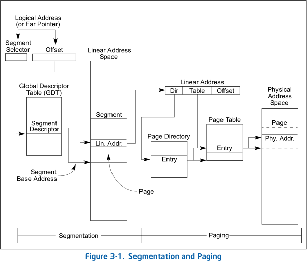
In contrast to real mode segmentation, segmentation in protected mode doesn’t use segment address directly to add it with effective address(offset). OS uses base address as index to one of system tables - GDT(Global Descriptor Table) or LDT(Local Descriptor Table). This is segment descriptor layout:
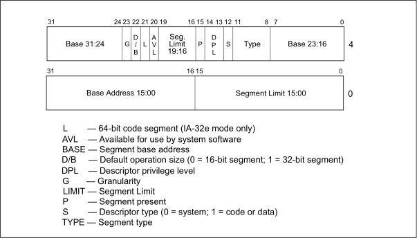
OS retrieves 8-byte segment descriptor, and finally reads base field in it to add it to offset.
Note there is DPL field, it contains the number of ring the segment belongs to. OS checks this information to determine program’s privileges to use computer’s memory.
Another feature is paging. Paging is another model of memory management. Now you also have pages alongside segments. The main argument to introduce paging was reducing of memory usage by system. As modern systems evolved to have multiprocessing, all memory inside OS is divided between different programs being executed simultaneously. Everytime you launch a new program, it makes request to OS to dedicate pages of memory for itself. But what if it doesn’t have enough memory? If it doesn’t, it can find programs that don’t actively use RAM and offload their pages to permanent storage, like hard drive. Old program frees space for another. This is how OS can find memory for programs which really need it. If the old program tries to access one of its memory pages, OS detects it and loads offloaded page back into RAM. If it can’t find free-to-use memory, processor generates exception telling the OS it can’t use enough memory.
Paging uses a bit more complicated addressing scheme. When segmentation used only base and offset to get memory address, paging uses a lot of different paging tables, and one last offset to them. This picture gives a little overview:
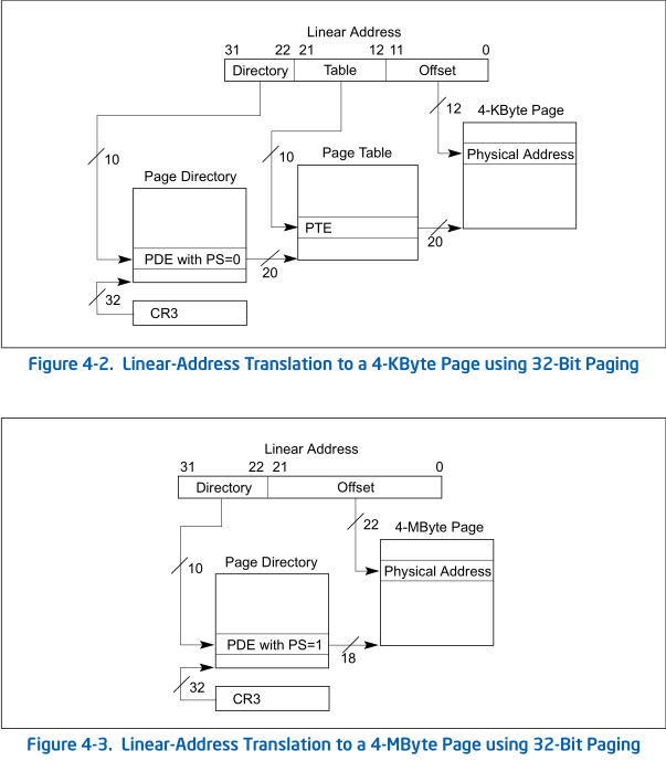
You can disable segmentation on processors which support paging. If you disable segmentation, all - or most of segment registers - will contain zero base address. It won’t be used to produce linear addresses, only offset will count. Linear address will be converted to virtual address. This is the hierarchy of addressing on modern x86 processors.
Any OS you use nowadays implements virtual addressing. Now every program you run has its own separate address space to run programs.
Modern systems don’t use segmentation anymore because they switched to paging altogether. But they still use some of segments(normally it is FS and GS) for their own purposes.
Executable File Formats
Due to historic reasons, there is a lot of executable file formats, I will take to review only PE and ELF file formats. They are most commonly used on Windows and UNIX systems respectively.
ELF and PE are complex file formats used to store executables, object files, and libraries. They are supplied with a lot of information about binary file. But I’ll provide only the information which is basic for reverse engineering process.
This picture clarifies a bit about ELF structure.
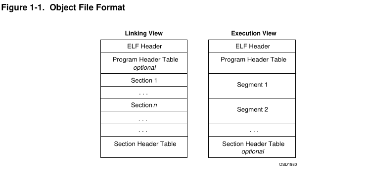
ELFs contain sections, those are regions of data used for linking and execution process. When program gets loaded into RAM, it doesn’t contain all sections, only those needed for execution process. OS composes segments from selected sections and loads them to RAM to make program work. Segments and sections differ because segments are actually ELF file’s sections mapped to memory, sections themselves are stored in permanent storage.
ELF files have program and section header tables. Program header table tells the system how to make up executable file using segments. Section header table only describes file’s sections(access rights(Read, Write, Execute), size, starting address, etc.). ELFs can contain both of them at the same time.
Both ELF and PE formats have symbols. Symbols are just names for variables and functions, normally coming from dynamic libraries. They are generated during compiling process to facilitate linking and relocation. This is hard topic, but maybe I’ll cover it later.
Important sections in ELF file:
-
.text - program’s instructions made by compiler
-
.data - data used by program, normally global variables end up here
-
.rodata - read-only data, global const variables
-
.got - Global Offset Table, global variables used by other program components, like libraries
-
.got.plt - Procedure Linkage Table, used to call functions from libraries
-
.bss - uninitialized data; big chunk of memory filled with zero values. (Static) global uninitialized variables get here
-
.dynsym table of symbols imported from dynamic libraries
PE format is not very different. It contains small MZ executable in its very beginning. If executable file were launched on DOS system, it would tell this file is for Windows only, otherwise it runs as expected. PE executable files have resources. Resources belong to an executable file, and comprise file’s images, fonts, binary data, and icons. A module is a binary file loaded into memory.
Important sections in PE file:
-
.text - same as ELF
-
.data - same as ELF
-
.rdata - same as .rodata
-
.bss - same as ELF
-
.rsrc - resources
-
.edata - export functions data, information about functions exported by PE file, normally only libraries export functions
-
.idata - data used to call functions from dynamic libraries(import data)
References:
Intel Manual Volume 1: Basic Architecture
Intel Manual Volume 2: Instruction Set Reference
Intel Manual Volume 3: System Programming Guide
Intel Manual Volume 4: Model-Specific Registers
Please, leave comments on what you think about this post.